





NewsDetails
Hole-based Flexible Welding Platform: Structural Strength Explained
author:jinchang time:2026-06-18 12:51:45 click:145
Structural strength is the first requirement that must be met before any other - accuracy, repeatability, and flexibility all depend on the platform remaining rigid and stable under load. A hole-based flexible welding platform used in industrial welding operations must resist deflection from workpiece weight, withstand forces from welding thermal cycles, and maintain its dimensional integrity through years of repeated use. This article examines the engineering factors that determine hole-based flexible welding platform structural strength and provides practical guidance for selecting and maintaining a system that performs reliably under demanding conditions.
Engineering Principles Behind Platform Rigidity
Rigidity in a hole-based flexible welding platform derives from three engineering properties: material stiffness, cross-sectional geometry, and support structure. Cast iron offers approximately 100 GPa modulus of elasticity while steel offers approximately 200 GPa - making steel nominally stiffer per unit of cross-section. However, cast iron's superior vibration damping and thermal stability often make it the preferred choice for welding platforms where heat-induced distortion is a concern. The base plate cross-section (thickness and any reinforcing ribs) determines bending resistance under load. A thicker plate deflects less, maintains flatness better, and resists impact damage more effectively.
Base Plate Thickness and Load Rating
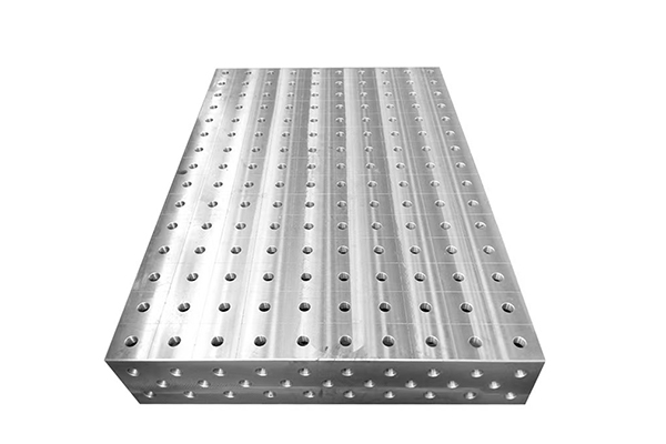
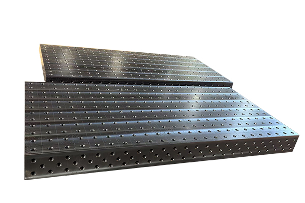
Base plate thickness is the single most important factor in hole-based flexible welding platform structural strength. Industrial welding platforms range from 25 mm thickness for light applications (parts under 100 kg) to 60 mm or more for heavy-duty operations (parts exceeding 1,000 kg). As a general guideline: 25-30 mm plates suit light fabrication and prototype work, 40-50 mm plates handle standard production welding with parts up to 500 kg, and 50-60 mm plates support heavy structural components and high-force clamping. Manufacturers provide rated load capacities for each plate thickness - always verify these ratings against your maximum expected workpiece weight plus a safety factor of 1.5 to 2 times.
Reinforcing Structures and Rib Design
Beyond thickness alone, the internal structure of a hole-based flexible welding platform significantly affects its strength. Quality platforms feature cast rib patterns on the underside that increase bending resistance without adding excessive weight. These ribs run perpendicular to expected load paths and connect to mounting points. For bolt-on or modular table systems, reinforcing cross-beams beneath the top plate distribute loads across a wider area, reducing local deflection. When evaluating platforms for heavy-duty applications, examine the underside structure: a flat plate without reinforcement will deflect noticeably under loads that a ribbed plate handles without measurable deformation.
Welding Force Considerations
Welding generates forces beyond simple workpiece weight. Thermal expansion and contraction during welding create internal stresses that can cause temporary plate warping. Arc weld forces (particularly with high-amperage processes like submerged arc welding) create electromagnetic and mechanical forces at the weld pool. A hole-based flexible welding platform must resist these dynamic forces without permanent deformation. Cast iron's ability to absorb vibration and resist permanent deformation under thermal cycling makes it particularly suited for high-amperage welding environments. For continuous welding operations on heavy components, consider platforms specifically rated for welding duty rather than general-purpose fixturing.
Hole Grid Integrity Under Stress
The hole grid is the functional core of a hole-based flexible welding platform, and its integrity under stress directly affects both structural strength and positional accuracy. Each hole acts as a stress concentration point - the surrounding material must resist deformation from clamping forces, pin loads, and workpiece weight transmitted through locating elements. In properly designed platforms, hole spacing accounts for this stress concentration: holes are positioned far enough apart to prevent overlapping stress fields while close enough to provide the fixture density that complex configurations require. Reamed holes with hardened surfaces resist wear and deformation better than threaded holes alone.
Load Testing and Verification
Before committing a hole-based flexible welding platform to production use, perform a load verification test: (1) Position dial indicators at multiple points on the plate surface. (2) Apply a test load equal to your maximum expected workpiece weight plus safety factor at the most demanding fixture configuration. (3) Record deflection at each indicator position. (4) Remove the load and verify that the plate returns to its original position within 0.02 mm (elastic recovery). Any permanent deformation exceeding this threshold indicates the plate is undersized for the application. Document these test results as baseline data for future comparison.
Comparing Platform Materials for Structural Performance
Three materials dominate hole-based flexible welding platform construction: cast iron, steel, and aluminum. Cast iron offers the best balance of rigidity, vibration damping, thermal stability, and cost for most welding applications. Steel provides the highest absolute stiffness but lacks cast iron's damping properties and is more susceptible to thermal warping. Aluminum is lightweight and corrosion-resistant but deflects significantly under heavy loads and is unsuitable for high-amperage welding. For structural strength in demanding industrial welding environments, cast iron remains the industry standard.
FAQ: Hole-based Flexible Welding Platform Structural Strength
How much weight can a standard hole-based welding platform hold?
It depends on plate thickness and material. A 40 mm cast iron plate typically supports 500-800 kg distributed load. A 50-60 mm plate supports 1,000-2,000 kg. Always refer to the manufacturer's rated load capacity and apply a 1.5-2 times safety factor.
Does welding near the base plate damage its structural integrity?
Direct welding on the base plate will damage it. Use spacer blocks and heat shields to keep weld heat away from the plate surface. Occasional proximity welding (welding workpieces mounted on the platform) is acceptable if the plate is cast iron and rated for welding duty.
Can a damaged base plate be repaired?
Minor dents and surface damage can be repaired through machining. However, deep gouges, cracks, or permanent warping compromise structural integrity and may require replacement. Consult the manufacturer before attempting repairs.
Why is cast iron preferred over steel for welding platforms?
Cast iron provides excellent vibration damping (important for weld quality), better thermal stability (less warping under heat), lower cost per unit of rigidity, and self-lubricating properties at hole surfaces that reduce component wear. Steel is stiffer but less practical for most welding applications.
Conclusion
Structural strength is the foundation upon which every other performance characteristic of a hole-based flexible welding platform is built. By understanding the engineering factors that determine rigidity - material selection, plate thickness, reinforcing structure, hole grid design, and welding force management - manufacturers can select and maintain platforms that perform reliably under the most demanding industrial welding conditions. A well-chosen, properly maintained platform with adequate structural strength provides years of accurate, distortion-free service, protecting both product quality and the capital investment in modular fixturing technology.
References
Bi, Z.M. and Zhang, W.J. (2001). Flexible fixture design and automation: Review and future directions. International Journal of Advanced Manufacturing Technology, 17(4), 266-277.
Rong, Y. and Bai, Y. (2000). Modular fixture element assembly and accuracy analysis. International Journal of Production Research, 38(14), 3103-3114.
Wang, Y. et al. (2019). Distortion mitigation in automotive welding through optimized clamping sequences. Journal of Materials Processing Technology, 270, 188-199.
 Recommended Products
 Contact Us
—— Hotline:+86 13833738896
—— Hotline:+86 17332777263
—— Email:gongliliangju@163.com
—— Whatsapp:+8615832706206
—— Whatsapp:+8615931710409
—— Address:Beihan Village, Haocun Town, Botou City, Cangzhou City, Hebei Province, China